This week’s focus has been entirely around the environment art and level design pipeline, where most of my time has been spent in Substance Designer creating procedural materials, and setting up environment shaders using the base master shader system previously set in place.
I have also started developing another level design tool to vastly speed up the workflow of placing and changing buildings (go to the end). I also heavily apologise in advance to anyone reading – this week has been beyond productive (great for me) so there is a lot to say!
PCG – Substance Designer
To speed up my workflow I use PCG (procedural content generation) a lot, and part of that workflow is setting up tools to re-use and speed up my workflow even further, as well as produce substances which can be re-used easily as functions.
For example creating stone/rock/concrete based materials is a very common occurrence for most projects, and this one is no exception – so to speed up the look-dev process I have condensed the usual process of utilising the slope blur node with noise maps and then adjusting all those settings and adjustments to the 2 inputs into a single node with all the default values set up to values more pertinent to my use-case and a lot more controls all within a single node.
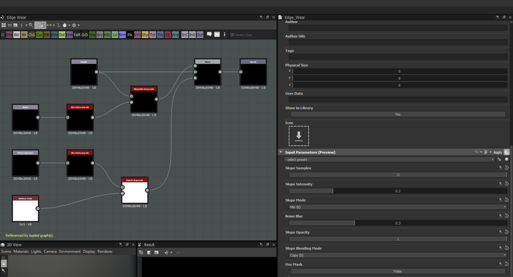
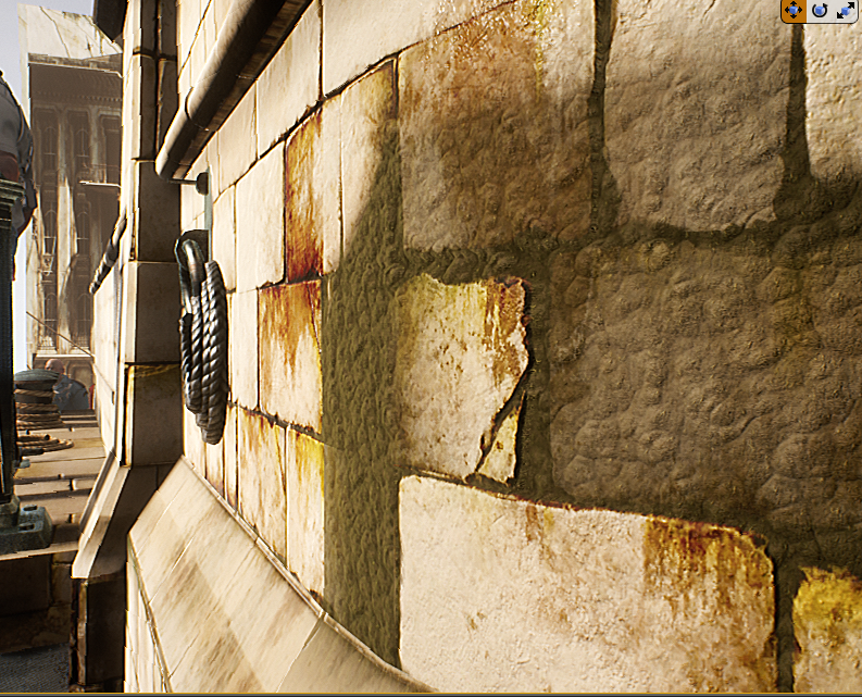
While it may seem like a small graph – it is a huge time saver and speeds up the look-dev process a lot and allows me to make very small scale layers of different types of wear. These bricks for example utilises that node a lot of times on a small scale to build up the detail without becoming too noisy.
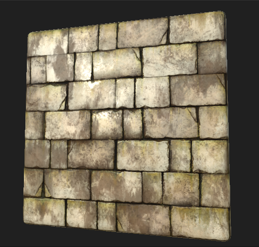
My general process for this substance is my default workflow where I will use a tile sampler to define the large shapes and general pattern first, and then refine the pattern inputs (will still being on the basic grey-box stage) to get the normal and height maps right (normal map is derived from the height – which is the focus).
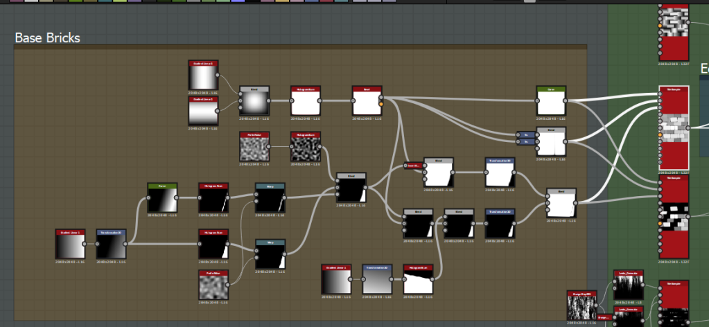
I then expose the parameters of the base tile sampler and duplicate the tile sampler node for differing inputs which all follow the same base parameter inputs (so they all line up). I then alter the scale, rotation, colour variation variation values etc to add micro-variation, and depending on the substance I add more inputs (I did here to add a cracked brick variation). This is all then blended with edge wear and gradient tiling to add different slopes and variation.
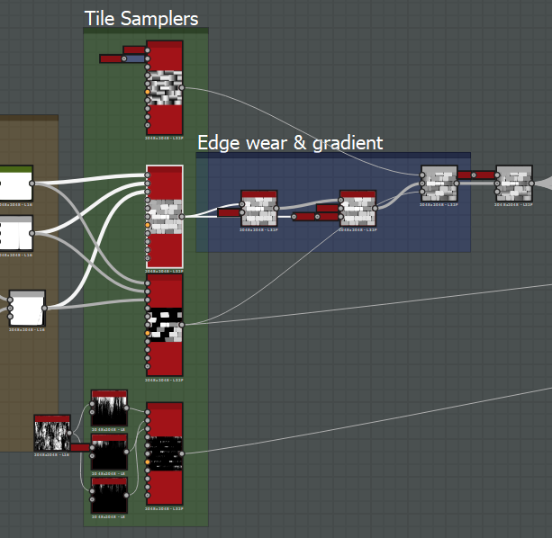
I then extract the normal and AO maps, then curvature sobel and curvature smooth from the normal map. The albedo is first generated by blending the height map with some grunge, and running it through a gradient map to remap the grayscale map into a colour range (I start quite subtle and desaturated with some variation). I then start adding in detail for this specific substance in the cracks and adding dirt, leaks etc. My process always uses the curvature maps overlayed on the albedo to add in the cavities and edges (which is still physically accurate) and the ambient occlusion map slightly to add a bit more depth (as the style requires it). In this case I also use the normal map to define the tiniest bit of directionality in the texture (again for the Dishonored style). Some final touches are made, a dirt/moss pass is added, a slight slope blur is applied for the painted look, and then the texture is sharpened.
The roughness map is a similar process of levelling out the height map, overlaying noise, overlaying ambient occlusion to occlude specularity in deeper areas etc and finally sharpening.
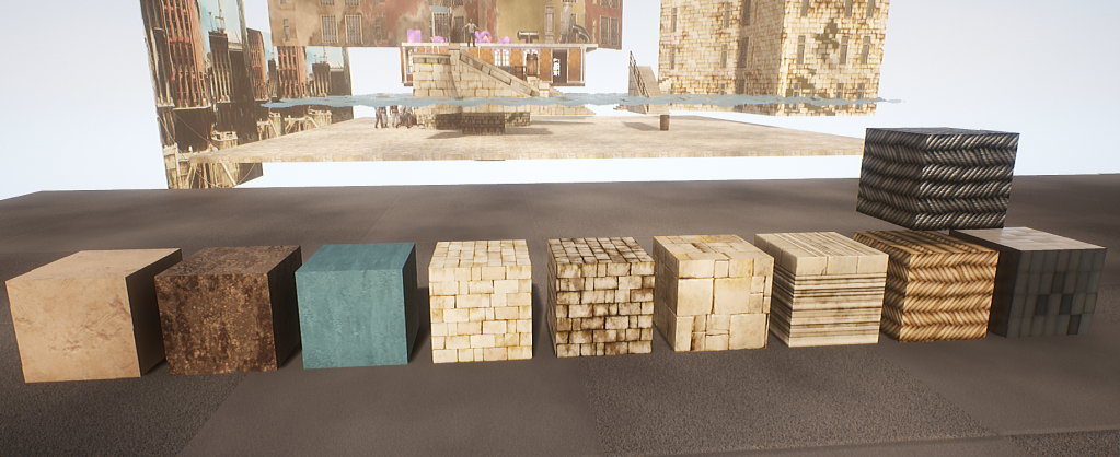
These are all the materials I ended up with in the end (not including variation instances apart from the rope instanced as steel cable). They all went through the same Substance Designer workflow with the exception of the stone trim (3rd to the right) which was done in 3ds Max > ZBrush (for edge wear) > Substance Designer, and the painted plaster (3rd to left) which is entirely procedural in the shader. All of these utilise all the shader features I set up previously and vary these properties in other instances, as well as some of them utilising vertex painted texture variations (clean to dirty plaster for example).
Modular Pieces
With all these materials set up in my master modular 3ds Max file (which were broken down from heavily analyising reference images into the core of what I need) I was able to easily create these modular pieces and testing them in-engine. I waited until some of the previous textures (the stone ones specifically) to be completed first as the modelling requires me to first apply the textures in many cases to keep it tiling – otherwise it would have caused me to have to re-work blockout pieces which is unnecessary in a one man team where I would have had to do this eventually regardless.
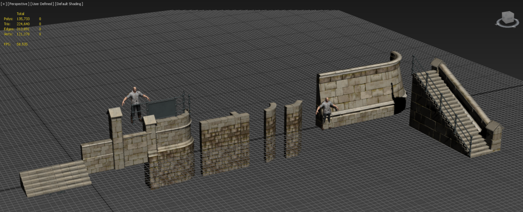
I’ve also started working on basic buildings to test the building pipeline and scale – more complex pieces and variations will be brought in as this further solidifies.
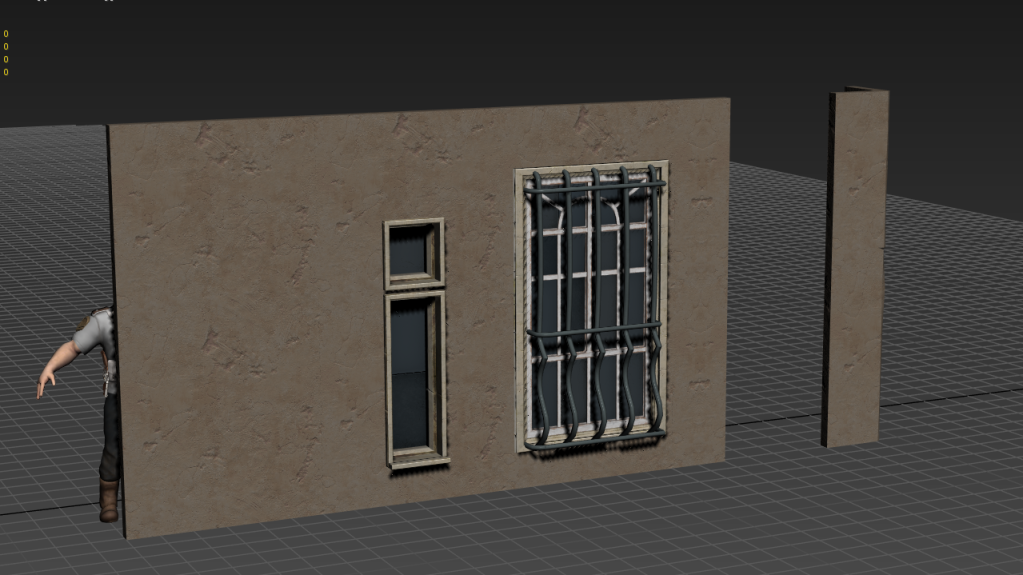
To test how they fit together, collisions, climbing functionality etc I have a lot of back and forth between UE4 and 3ds Max (which is made easy with a batch exporter I written before this project in MAXScript). The general texturing workflow involves me modelling with what I want to use on which textures in-mind, applying the right material IDs, then unwrapping around these areas. This often involves a lot of planar and cylinder maps, and flattening a lot of other areas in order to pack and move them onto certain shapes and bevels.
Trims & Material Instances – Why?
The advantage of this environment workflow is it heavily reduces draw calls as I’m not generating unique textures for everything. It also allows me to create many small props using these materials and still retain a very high level of detail at a very fast pace.
Doing this also allows me to very quickly vary up the look dev and add in variation using material instancing (which re-uses the textures in many cases, keeping variation textures to a minimum to save on texture memory).
When I’m defining what I need to make I first define real world materials of referencs and what makes up what I need, if there’s too much going on or it’s too unique (like many props are) then it requires a unique texture set, otherwise I will utilise this workflow to gain and immense amount of high quality detail. Using material instancing also allows me to link them up to gameplay using physics materials – for example different materials are set up to trigger different footstep audio based on the physics material of that material instance.
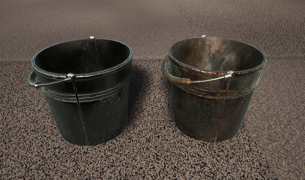
This bucket for example is made using trims very quickly and is varied up using the rusty metal trim instance.
Or these bollards which demonstrate this workflow on props perfectly – where these all use the same set of materials (and a rusty variation set) but completely changed up within the material instances without changing the textures. These were originally made for the pipes but they demonstrate how the workflow even allows me to retain edge wear because of how I’ve applied these textures and how the textures were made – no fancy tricks (for me anyway), just HSV & contrast adjustments to the albedo, and levels to metalness and roughness values.
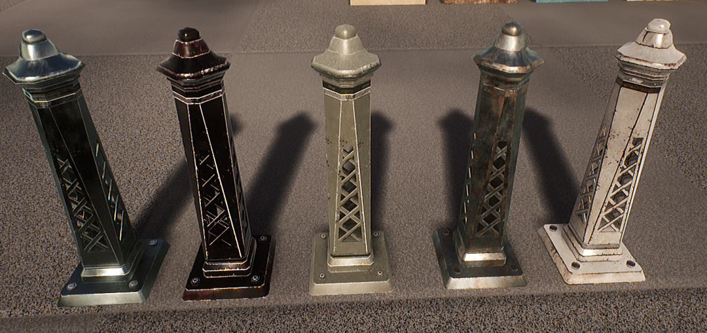
Detail normals are also used on most of these instances to give them that slight boost in detail when up-close (they are faded out based on an adjustable camera distance). This fits in with the style to give the detail needed when up-close to be believable, but also not noisy when viewed from a distance. Roughness grunge maps are also offset randomly based on the world position of the object, meaning it will automatically give a slight variance to each prop without me doing any work other than moving it.
Using this workflow has allowed me to produce incredible amount of environment of very heavily re-usable props and modular pieces in such a short amount of time (with a lot of help with the shaders – more on that next).
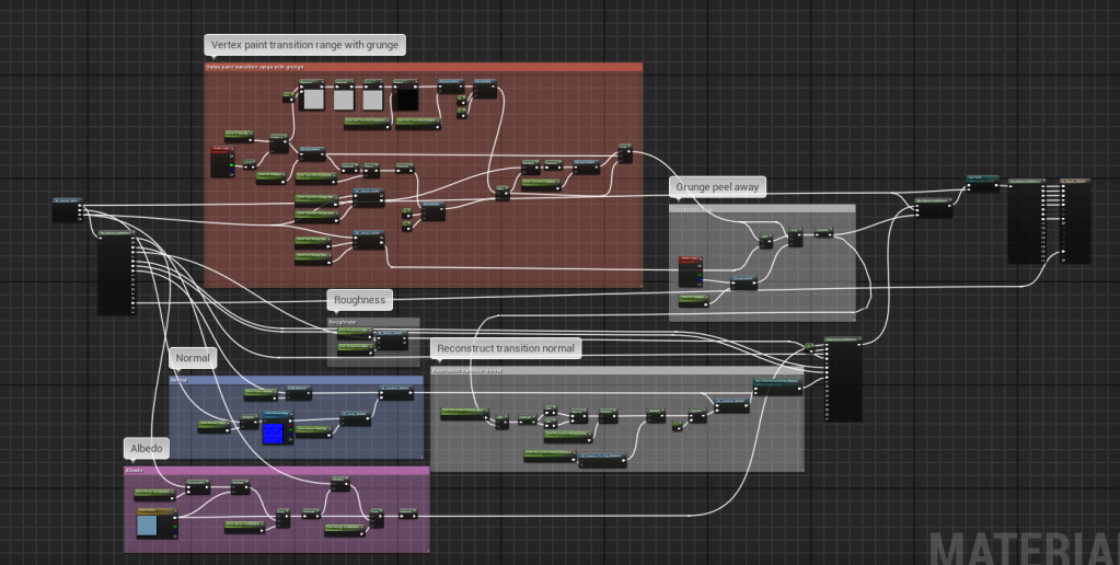
Shaders for Days!
Anyone who knows me will recognise my love and passion for shaders and their beautiful combination of high level art-based workflow with basic interaction with the GPU – here is no exception and all of my work this week pivots on the use of shaders.
This week specifically I have developed a master shader for stone to add moss, master shader to add paint (and strip it away) on plaster (for buildings), a randomising decal atlas shader, a master window shader with a reflection offset interior, and a screen space underwater caustics shader.
That’s a lot to digest so it’s best to break each one down first, and I’ll talk about the screen space underwater with the water volumes as there’s some more tricks there.
Master Stone – Moss Blending
To expand the functionality of the base master shader I added moss blending for stone, where this supports fuzz shading (helps give the moss that specific look), colour, roughness, 2 layers of normal etc.
This is very easy to adjust as the moss is being reconstructed from the moss I made in Substance Designer which is packed into 2 texture maps to save on texture memory and texture fetches. The first map stores the greyscale/curvature/ambient occlusion/larger greyscale maps all in one texture in RGBA with DXT5 compression, and another texture map which packs the RG channels of the microdetail and larger detail normal maps into RG and BA respectively. This is possible for normal maps as the blue channel is often devoid of detail and is usually about 1 – meaning approximating the blue channel as 1 when reconstructing the normal and remapping into -1 to 1 space will have very little to no change. I did this on the normal maps to adjust the larger bubble-like detail and micro fuzz detail independently – meaning I can create different moss types in material instances.
This is backed up by parallax offset using the packed greyscale map as a height map, and the base functionality of painting in variation textures (for thinner moss leaks).
Master Plaster – Paint Blending & Stripping
Similar to the moss blending I have default to a dirty plaster material built into the base master shader functionality which is useful for adding worn areas towards edges and at the bottom wear the plaster would dirty and erode away.
To expand this functionality I have made it so the plaster material defaults to being completely painted (for the sake of buildings and easiness) and you can use vertex painting to erode away the paint, and blend in grunge maps to wear the edges of the paint away. This is all done by re-using the grunge maps calculated for roughness variation in the master shader and only one normal map for the paint – the rest is done through blending in albedo and roughness values on-top without any extra textures so that it remains optimal. The albedo of the paint is also varied using the grunge maps to add that slight variation, and by default the plaster material is projected using triplanar projection as it makes the most sense for large scale buildings.
To further emphasis the look of it being paint I have a detail normal for the paint which is blended on-top of the base plaster normal (which is flattened by an adjustable amount) to give the illusion of multiple layers of paint.
And to give the paint more depth when up-close I constructed a procedural tangent normal to blend in by getting the delta rate of change between neighbouring pixels for the transition calculation using DDX and DDY – this quickly helps me generate a tangent normal where the worn away edges are to make the paint appear like it is on-top and remain procedural. This effect is again scaled on camera distance so it doesn’t appear too noisy from far away.
Master Decal Atlas – World Position Randomisation
Vertex painting can only get you so far so I’ve started my decal workflow with a randomising decal shader which randomly offsets the currently selected frame in the texture atlas based on world position.
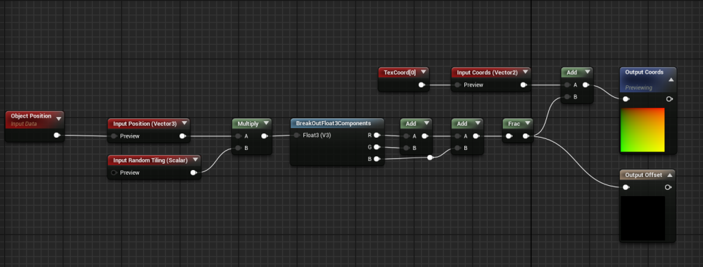
This random offset is calculated by multiplying the world position (or object position for decals) by an amount (to increase or decrease how much you need to move before it changes frame), and then adding the XYZ components together, and getting the fraction to get a pseudo-random value between 0 and 1.
To actually create the leaks I created a Substance tool which generates leaks using input noise maps to distort and directional blur a pattern generated from the built-in waveform node. I then just used these nodes with different inputs (and randomised seeds) to generate the maps I need and input into a node which generates an atlas from its inputs.
I didn’t make the atlas node, you can find Atlas Maker here – https://share.allegorithmic.com/libraries/18
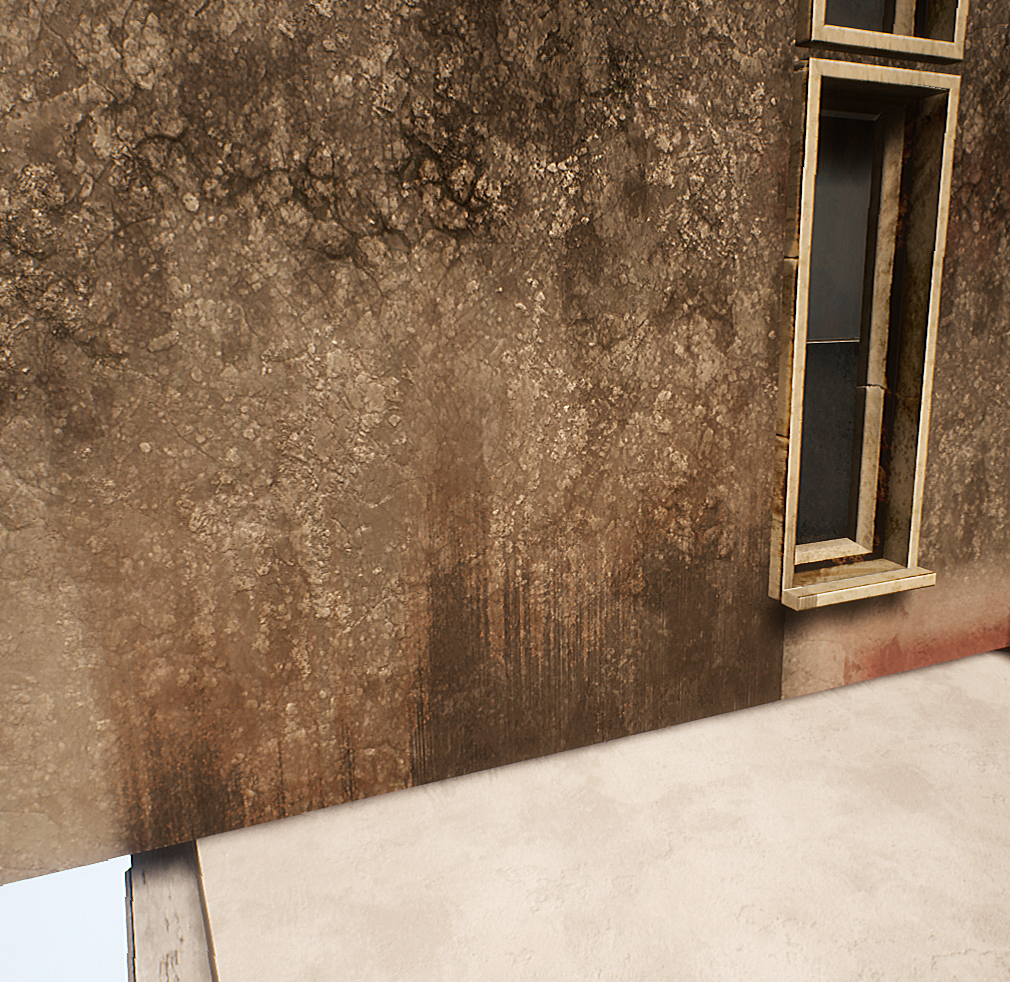
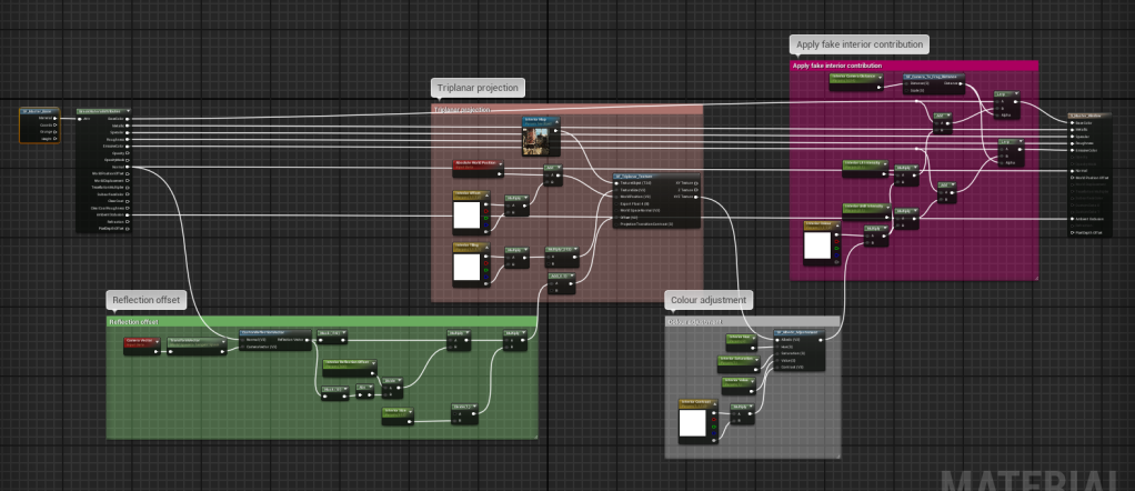
Master Window – Fake Interior
This shader simply takes an input texture map and samples it in world space using triplanar projection and then offsets the coordinates using a technique similar to parallax (bump offset) but with the vector travelling through the mesh for a more accurate effect. The result is then added to both emissive and albedo outputs and can be varied up easily, where I plan to accept an atlas instead and randomly choose a frame based on world position (similar to the decal atlas shader).
On-top of that the shader is very specular and glossy, as well as having a dark albedo to hit the right amount of energy conversation to get the effect I want.
This effect is also enhanced by the slight variation in the normal map which is used when sampling the reflection vector in tangent space, so intensifying the normal map applies an offset to each tile of the window. And to prevent too much repetition, the effect is scaled based on camera distance to the current fragment (pixel) so that it fades out at a distance where you shouldn’t be able to see it regardless.
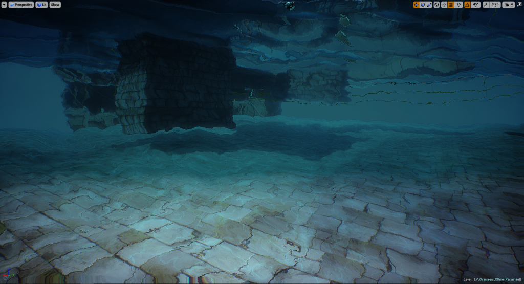
Water Volumes
I created a blueprint to handle large bodies of water visually and gameplay-wise, where it uses a physics volume to actually handle the swimming aspect (built-in support with the default character controller).
Visual-wise when underwater it uses a post process volume scaled to the same size as the physics volume (all handled in blueprint so you just scale the volume and it will work), with some post process effects and 2 post process shaders to apply the distortion effect, and screen space caustics with added depth fog to give the illusion of light being brighter in front of you. The caustics are done simply in a texture which is panning 2 noise maps to distort the coordinates of the caustics cells texture, and the base coordinates are simply grabbed from the world position buffer so they are mapped in world space – I did this to avoid having to create a material to handle caustics or use decals and light functions which would mean having to add lights/decals underwater and dealing with overdraw.
To keep the water volumes optimised I have the top water plane being calculated with masked dithered opacity which is cheap and only has overdraw where it intersects with objects (to give the fading effect), but the plane when underneath is the same plane but flipped (so it flips the normals) and renders that plane instead of the top one (and vise versa when above) due to it being culled by backfaces in the winding order.
This means I can have the plane be translucent when underwater using material overrides on the water material instance to force it to be translucent and retain all its values to give it that specific look-dev on the waves etc.
To get to the point of why – this is so I’m only paying for overdraw when I really have to which is when you look up underwater. Below is the shader complexity (which rises with overdraw) of the framebuffer when above water (left) and below water and looking up (right).


Building Tiler – Level Design Tool
As I’ve been pulling in new modular pieces and tiling materials, there has been no better time for me to start developing a tool to speed up the level design workflow as it comes round. A big part of the environment consists of buildings which can be tedious to place piece-by-piece hand-by-hand, so this blueprint handles the tiling of pieces in X and Z (across and up) by dragging a marker gizmo in the editor.
This blueprint essentially tiles these meshes based on pattern meshes – which are defined easily by an array of static meshes. So dragging out the marker will tile the modular pieces in the order they appear in the array, and you can store multiple patterns and flick between quickly for easy randomisation. I also added support to offset the pattern so you can easily vary up or move pieces around but in a predictable and intuitive way.
As with the scrollable sets this also supports material overrides which will be very helpful when creating different coloured buildings.
Where Now?
This week has been very art and level-focused in order to save time down the road as many of these tasks are dependent tasks which other tasks depend on before being able to start (such as the level itself).
Next week I will bring the focus back to VFX and gameplay by starting to concept the abilites, refine the blink ability, refine and add more enemy character animations – and I’ll see what else it brings!
Well done if you made it this far, I again I apologise for the long blog post but this has been a productive week and I hope this helps anyone reading with a further insight into a game-ready environment workflow.

I love reading those blogs!! Small question, how did you get the edge wear on the bollards using trims and not a curvature map?
LikeLike
Thanks man! I hope to keep producing blogs for my next project too. The edge wear on the bollards was produced in the trim itself. and then I just mapped the mesh to those pieces. It was, if I’m honest, a happy mistake by just how the material itself turned out with all the bevels and edge wear baked into the material itself – but if I wanted to make dynamic wear I would do a material blend in the shader using a pre-baked mask with a wide linear mapping range.
LikeLike
Hey. Awesome work. Sometimes I don’t understand how set-up the shaders (e.g. glass one) and the screenshots are a bit too low res, so I can’t see them on my own. Can you maybe make screenshots a bit more high-res, so I can learn and maybe still some of your ideas ? 😀
LikeLike
Hey, I’ll get around to that at some point 🙂 the glass is a bit fiddly but the main idea is just using sphere masks (GenerateBand node) with reflection vectors to generate the fake anisotropic highlight. And then a fresnel with a tangent->world normal to add the noise in the refraction.
LikeLike
Hi. Awesome article. I want to ask about paint layer procedural normal transition. The blueprint image are so blurry I cant understand how did you set it up. I know you used DDX/DDY but I cant find any useful information about those nodes. UE4 documentation just says almost nothing about them. Can you somehow explain how did you set the material? Thanks. ))
LikeLike
Hi Tural, sorry about the blurry images (didn’t realise at the time they would turn out blurred).
The ddx() and ddy() functions are HLSL intrinsics which return the derivative of the neighbouring pixel (as pixels are processed in parallel on the GPU). In layman’s terms this just means you get the the difference with the pixel’s nieghbour. You can use these to generate a normal if you append the result of ddx and ddy of the sampled height/alpha at that point, and you can then use DeriveZ to derive the z component – hope that helps 🙂
LikeLike
Oh big thanks for fast answer. So, what I understand… Lets say I have vertex color or grunge map which I want to paint a new layer with. I can append the ddx and ddy of that map, then derive z from that information and blend tiled normal map of the layer I want to paint with derived z information and it will give me elevation of that paint layer with its own tile normal texture on it? Am I right?
And what about performance? Do you think it is cheap for VR?
LikeLike
Yes but it will be dependent on how close you are to the surface as ddx() and ddy() are the pixels in screen space.
There should be next to no cost on most devices because the reason you can access the neighbouring pixels on a hardware level is that the GPU executes pixels in parallel, so the other pixels are in buffers already.
I don’t know how this works on VR though because of the stereoscopic display. I would imagine there would be issues there.
You should read this as it explains those HLSL functions in mode detail 🙂 http://www.aclockworkberry.com/shader-derivative-functions/
LikeLike
Oh thank you so much for taking time and explaining. I will read the article. Cant wait for weekend to go home and experiment with this. ))
LikeLike